Recently a 2006 Chevrolet Impala came into one of our retail locations with a surge complaint while cruising on the highway between 60-65 mph. I drove the vehicle with the customer to verify the concern and was able to duplicate the circumstances in which the vehicle acted up. While watching the tachometer I noted that there was a noticeable 150-200 rpm surge while TCC was applied. It felt like a typical TCC surge as a result from a leak in the TCC regulator circuit, so additional diagnostic steps were in order. We discussed this with the customer, and he authorized the additional time. At this point I was fairly convinced that we were going to need to go inside the unit.
We always start our evaluation with some pretty basic steps: check fluid level and condition, scan for codes, perform a battery and charging system test, and an undercar inspection. At this point everything was looking good, fluid was full and clean, there were no DTCs for the engine or transmission, and the battery and charging system test results came back error-free, and there were no obvious problems shown with the visual inspection.
At this point we proceeded to take the vehicle out for a road test with the scan tool connected so that I could monitor the PIDS for the TCC command while looking at the TCC duty-cycle while the surge was occurring. It appeared that the PCM was commanding the change, although it was very erratic. Given this information, I now had to try to figure out what PCM inputs could be causing this to happen.
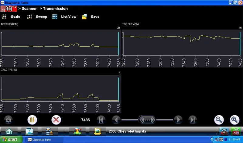
After a few considerations, I turned my attention to the TPS signal. Utilizing a Snap-On Verus Pro scan tool there is a PID called, "CALC TPS %" and while monitoring this value, I saw what was making the PCM vary the duty-cycle and therefore causing the TCC surge. There was a noticeable jump in the TPS signal when the surge was happening (Figure 1). As this is a "drive by wire" system, I also looked at the APP signal and it was smooth. Further testing was now in order.

Figure 1
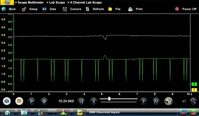
After looking over the circuit wiring diagram and connector view from GM Service Information, and also checking for pertinent TSBs, I hooked up the scope right at the throttle body to TPS1 and TPS2. At a throttle position just a little off idle, I could see the glitch in the signal in both of the inputs (Figure 2). After verifying there were no ground issues I was leaning toward recommending that the throttle body be replaced. One last thing I needed to check was if there were any updates to the PCM calibration. Checking the current calibration against the GM TDS website, I noted that there were several updates to the calibration, although none of them relative toward the issue that I was having.

Figure 2
My recommendations for repair included a pan inspection & fluid/filter change, a replacement AC Delco throttle body, and reprogramming of the PCM. All repairs were authorized by the customer and we proceeded with the repair. After my recommended repairs, drivability was normal, data signals were smooth, and the TCC surge was gone. The vehicle was then returned to the customer. Another one done, or so I thought.
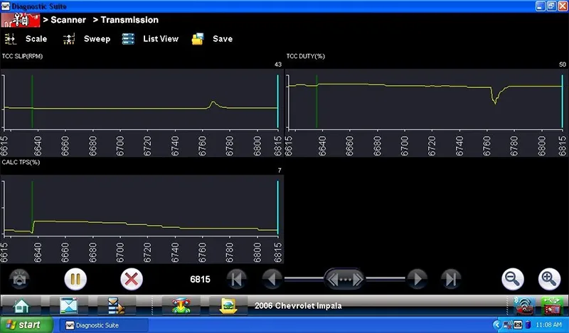
Unfortunately, two days after the vehicle was returned to the customer, he returned with the dreaded, "It's still doing the same thing." I grabbed the scan tool and went for a ride with him, and this time it took quite a while for him to get the vehicle to act up and it was not a repeated surge like it was before. However, under just the right set of circumstances you could see the tach rise up by about 50 RPM. This little RPM flare would only happen at very light loads. While I could see the duty-cycle command change when this happened (Figure 3), I could find no reason for why it happened as the TPS signal was smooth.

Figure 3
I then recorded all the transmission data so I could go back and look at it more in depth, to no avail. We again went for another road test while I was looking at the engine side of the data and happened to catch something changing when the RPM flare occurred. This particular vehicle has the "DOD System" (Displacement On Demand) where under light load conditions it can deactivate cylinders 1 and 7 on the left bank and cylinders 4 and 6 on the right bank at cruising speed. On the scan tool there is a PID called, "Cyl deact system command" that will either show V8 or V4 and this is where I saw the change: every time that the PCM commanded a change in state from either 8Cyl mode to 4Cyl mode or vice versa there was a quick dip in the TCC duty-cycle command (Figure 3).
It was more noticeable from V8 to V4 because of the light load, when going from V4 to V8 there was an increase in load that triggers the change in state and the small flare was not as noticeable. After verifying operation on another like vehicle, I have to conclude that this is a normal operation and just a byproduct of the change in state from V8 to V4 mode and probably programmed into the software to make sure the transition is smooth so the owners do not notice a bump or jerk during this transition. Since I am not a GM engineer, this last statement is just my opinion. I have never seen anything in print to 100% verify.
 Certified Transmission
