Earlier this year a 2014 Ford Explorer came into our shop with a complaint of setting code P0706 (Transmission Range Sensor "A" Circuit Range/Performance) and erratic and/or hard shifts at times. After studying the history of the vehicle, I learned that it originally had a similar concern diagnosed at a local Ford dealer, at which time a replacement transmission was recommended. The dealer had installed our remanufactured transmission at that time. The vehicle had returned to the dealer where the transmission was original installed and was now diagnosed as having a bad range position sensor. The vehicle was sent to one of our retail locations and a warranty claim was opened for the issue, and that's where this story begins.
With this information in hand I began my diagnosis with a scan check that showed a code P0706, P0707 (Transmission Range Sensor "A" Circuit Low), P1702 (Transmission Range Sensor Circuit Intermittent), and P1921 (Transmission Range Signal) stored. After a quick visual check, I noticed that the main engine harness was not fastened to all its retainers, but the connectors seemed to be seated and secure. (Figure 1)
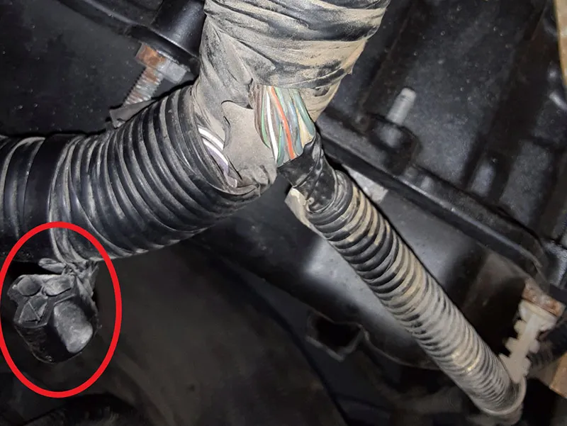
Figure 1
I took the vehicle out for a road test. The range sensor PID was showing all the correct gear positions and the transmission responded correctly, except for a single erratic downshift on a closed throttle coast-down that I could not duplicate again.
At one point I had stopped on a hill and went through all the gear positions again, and everything was fine until I started backing up the hill which revealed a change on the range sensor PID I was monitoring. Yes! Now I had witnessed an error that could be tracked down and knew how to recreate the issue.
Feeling that the condition occurred with potential movement from the engine/trans, I tried power braking the vehicle in reverse and I could duplicate the range switch jumping from reverse to drive and sometimes to park momentarily on the scan tool PID. I had an assistant hold the brake at idle and in reverse while I moved harnesses under the hood and could see the range position change when moving the main engine harness near the transmission.
Feeling confident that the problem was external of the transmission and not a warranty concern, we contacted the installing dealer for authorization to further diagnose and repair the harness and they agreed to allow us to continue.
After removing the air intake box and tube for access, I reconnected the scanner and started moving the harness while watching the range switch parameters while narrowing down the area that affected the readings. This brought me to the area of the harness where the transmission pigtail breaks out from the powertrain harness. Upon close inspection in that area, I didn't see any external damage to the harness, but there were uncovered wires at the point of the breakout. (Figure 2)
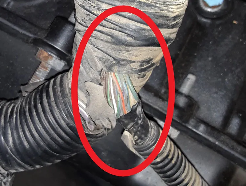
Figure 2
A study of the schematic showed a three-wire circuit for the range position sensor. (Figure 3)
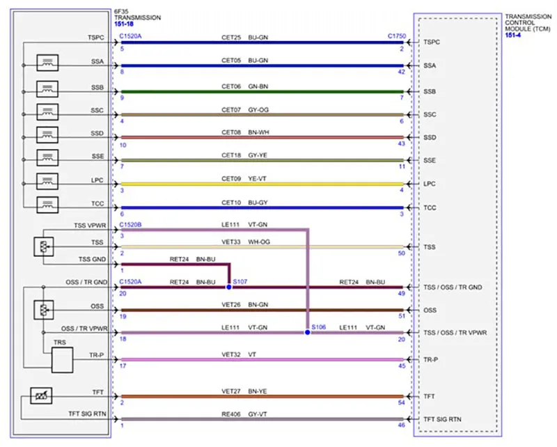
Figure 3
With the car powered down and the scanner removed, I disconnected the harness from the transmission and the TCM and connected an ohmmeter to the signal circuit of the range switch (pin 45 at the TCM and pin 17 at the transmission). When moving the harness around the meter never fluctuated, so I then moved the meter to the power circuit for the range sensor (pin 20 at the TCM and pin 18 at the transmission). This time while moving the harness, the meter fluctuated to various readings. With the condition still being most sensitive at the harness breakout, I started slowly cutting away the tape and opening the harness. With an ample amount of wires exposed, I started slowly separating wires to locate the VT-GN wire (circuit LE111) for the sensor power circuit and located splice S106 as shown in the schematic. (Figure 4)
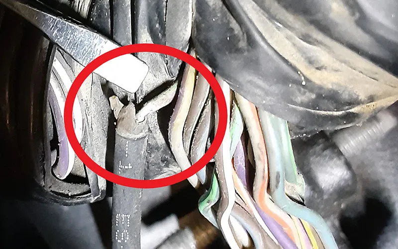
Figure 4
Upon closer inspection I could see the insulation grew thin at the edge of the splice indicating the wire possibly broken inside letting the insulation become stretched. As I moved the splice and circuit away from the rest of the harness my ohmmeter read OL and never showed continuity again. With a light pull on the wire the insulation stretched and separated revealing a broken wire. (Figure 5)
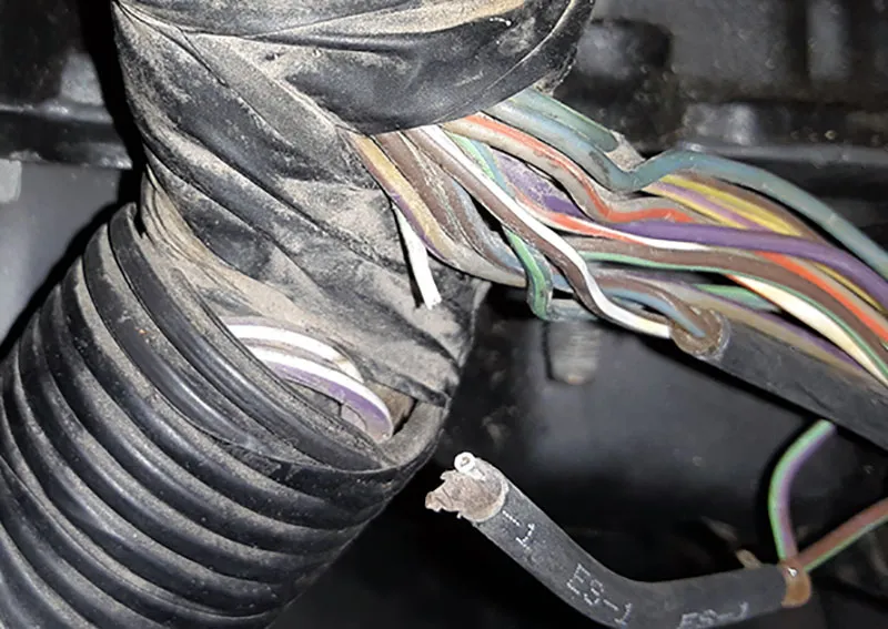
Figure 5
Now that I had located the cause, it was time to make my wire repair. In the past I have found several intermittent electrical conditions caused by resistance variations with temperature change and vibration due to poor splices over the years, so I won't use quick splices like butt connectors. I proceeded to cut out the splice, cut a replacement wire slightly longer than what I removed and stripped back the wire ends. Next, I slid a section of heat shrink tubing on my wire ends making sure I have 1-inch clearance from the stripped ends so that the tubing doesn't shrink during the soldering process. Lightly twisting the bare wire ends together in a straight line I now solder them together.
To ensure a weather-tight seal, after the solder has cooled I lightly coat the splice with liquid tape and let it skin over, but before the liquid fully hardens, I slide the heat shrink tubing over the splice and heat it from the center out to each end as not to trap any air inside. Now I can bundle the wires in the harness with tape and split tubing for protection from the environment and support for the wires.
When we are faced with intermittent conditions it always helps to take the time to gather all the information I can, study the history, and approach my diagnosis with attention to details and clues. Today's harnesses are made up with small gauge wires and are vulnerable to vibration and stretching if not routed and supported correctly.
Here was a condition caused from a harness not correctly supported, and its own weight and a little bit of movement proved too much for this small gauge copper wire. With the ECU processors reading low voltage/ low current variable signals, circuit integrity is becoming more and more important. When making repairs to a vehicle we need to make note of how harnesses are routed before we remove them and reinstall them properly and securely away from harm. This attention to detail will help prevent issues like these.
 Certified Transmission
