
Have you ever attempted diagnosing a vehicle with little to no information that will help lead to a quick and efficient solution? Taking the time to go through the diagnostic trouble–tree is useful in that it eventually leads you to the solution, however, having just a bit more information could have made a more efficient diagnosis and repair. Having more information would also help the customer save time and money.
My first experience with this type of problem was on a 2000 Toyota Land Cruiser. The customer stated it shifted fine, but the check engine light (CEL) was on with a transmission code. The stored DTC was P0773 (Shift Solenoid 'E' electrical) code. After clearing the code, the transmission would reset the fault code immediately after starting up. On the initial test drive the transmission would up–shift well but there was no torque converter lock–up commanded. The transmission fluid was full and a little off color, but not burnt. There was no sign of glycol contamination.
I was able to pull up wiring diagrams for the vehicle and found that the solenoid should run between 11–14 Ω. The powertrain control module (PCM) was located in the cabin next to the glove box and was easily accessible. I started my testing there and verified that the computer was sending voltage. My next test would be to check the integrity of the circuit. The circuit showed "open" when tested to vehicle ground. I then went down to the transmission and found that there was no voltage coming into the transmission end of the harness, and this was indication that there was a break somewhere in the harness. I made a temporary jumper using my back probes to see if the solenoid would activate on command. (Figure 1)
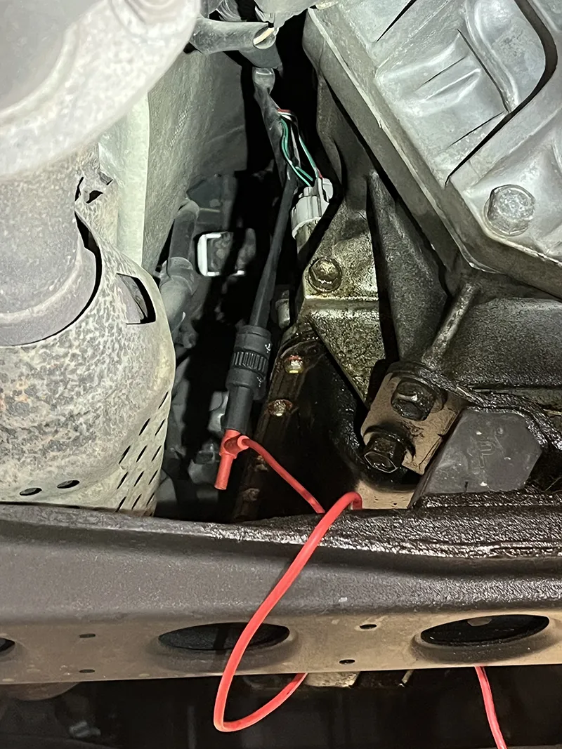
Figure 1
When running the temporary jumper wire from the firewall where the harness comes through from the cabin then down to the transmission, I found there was a passthrough connector at the top of the bellhousing straight down from the cowl of the engine. Nowhere on any of the wiring diagrams was there an indication that this connector existed between the transmission and the PCM.
Upon inspecting the connector, I found signs of water intrusion and heavy corrosion. The pin for Shift Solenoid E (also referred to "SL" or "lock up solenoid") was broken and no longer made contact. (Figure 2)
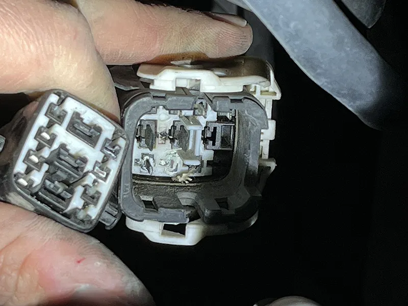
Figure 2
Several other pins had corrosion but were still in proper contact and making a connection. I knew I had found my problem, but I continued with my temporary jumper wire to confirm that the transmission would work once the circuit was repaired. Once the jumper wire was installed, I road–tested the vehicle and there no codes were set, and the torque converter operated as designed. I proceeded to wire a permanent jumper around the pass–through connector after cleaning the other connections and applying dielectric grease to prevent further corrosion. (Figure 3)
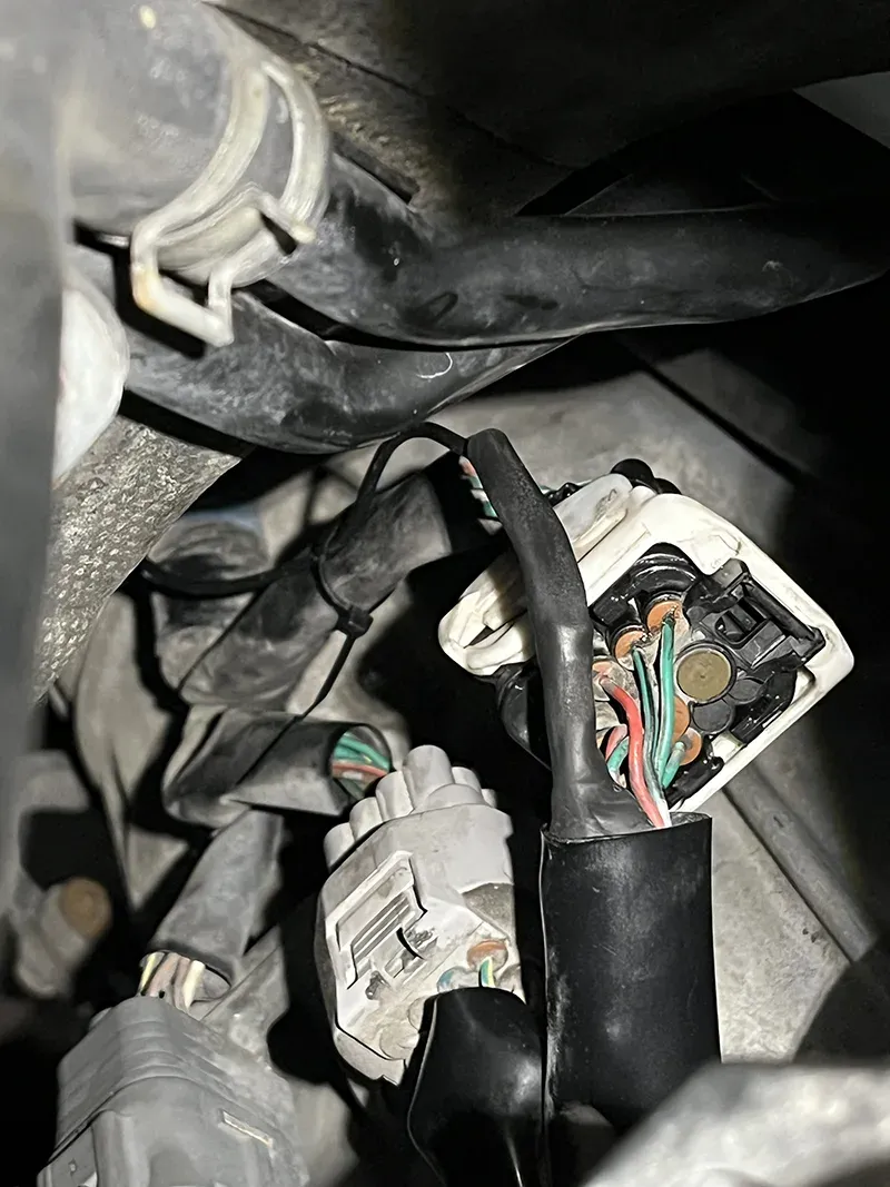
Figure 3
I checked several other sources and could not find any that showed this connector. If I had a wiring diagram that properly represented all the connections between the PCM and the transmission or had found information that the connector was prone to getting water from the cowl, my testing process would have gone quicker and more efficient, thus, saving the customer money and freeing up space in the shop for other vehicles to be diagnosed. Sometimes we just have to find out the hard way.
Another similar instance was a 2010 Mazda 3 with the complaint that after driving for a little while the transmission light would come on and the vehicle would struggle to shift. On my initial test I found code P0720, (VSS circuit malfunction). The transmission fluid was full and in good condition. Upon clearing the code, the computer would not reset immediately. The transmission would upshift well in gears 1–4, but there was no reading from the speed sensor, and the code would reset. This prevented the transmission from going into 5th gear or TCC apply. When reading procedures for speed sensor testing, you are looking for supplied voltage from the TCM (transmission control module) and a square wave pattern from the sensor.
When hooking up the scope at the sensor, I could see voltage being supplied and a solid square wave pattern from the sensor. I could get the same signal at the transmission control module connector, but the computer was not showing any speed on the sensor PID, so the signal was there from the sensor but not translated by the TCM. At this point I recommended a TCM replacement.
After installing the replacement TCM, I proceeded with another test drive. The speed would start to read, then go to zero, occasionally show speed but more often than not it still read zero and reset the code. I suspected that I may have missed an issue with the wiring. Further testing led to the same results, voltage from computer and a solid square wave. I tried moving the harness and connectors (wiggle test) with no change to my findings. That is when I noticed that even though my square wave was a good on/off, the voltage was only 2–3 volts. When you key–on, the control module sends out 5 volts. I replaced the vehicle speed sensor and achieved a good 5–volt square wave. The computer was now always receiving the signal and no codes were set.
All documented test procedures said to look for a square wave, but I couldn't locate a procedure that mentioned what the voltage of the square wave should have been. Again, if that little bit of information was easily accessed it would have saved me and the customer a lot of time and frustration. (Figure 4)
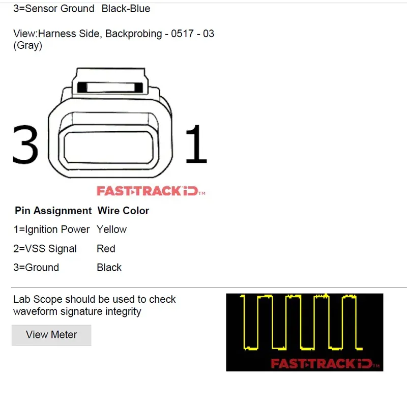
Figure 4
In conclusion, these two cars had quite simple repairs. Lack of information during the initial diagnosing made these otherwise simple repairs more time–consuming than necessary. By putting these little finds out there for other technicians, we can all help each other be more efficient in our diagnosing and repairs.