
A 2005 F350 Super Duty 5.4-liter engine with a 5R100W transmission was in our shop and presented with transmission diagnostic trouble codes. The codes were P0657 (Actuator Supply Voltage A Circuit/Open) and P0962 (Electronic Pressure Control Solenoid Circuit Malfunction). Technicians develop and apply their own styles and methods to any diagnostic situation. There are generally multiple paths that will lead to a correct diagnosis, and some that will not. In the end, everything becomes a process of elimination followed up with pinpoint testing for proof of failure.
When I approach diagnosis, I like to look for the most efficient way to find the problem. Since I am not familiar with these codes I am going to start with a complete understanding of the DTC, operation, and code setting criteria. First, we will start off with the theory of operation and code criteria, long before we get out any tools. Researching resources at the beginning of the process will pay dividends when the job is complete.
Researching the codes was the first step:
P0657:
Possible Causes Setting Conditions
- PCM connector is damaged (check pins for damage, and for moisture)
- Power (12v) circuit to the Actuator Supply 'A' circuit is open
- PCM has failed Engine running; and the PCM detected an open circuit condition on the Actuator Supply 'A' circuit for one second.
With this information known, we can already suspect the PCM is bad, or the circuit is open (broken wire), but let's move on and prove my suspicion.
P0962 is a circuit malfunction. The PCM detected a low voltage condition on the Electronic Pressure Control (EPC) solenoid circuit. "Low Voltage" means just what it says, the EPC solenoid is not getting the voltage it needs to operate. But how does the PCM know the EPC does not have enough voltage? Here is how:
In cases where a solenoid is powered by a relay, fuse or module, it uses the module to ground the circuit to actuate the solenoid. This is common on most American vehicles. When the solenoid is ungrounded there is voltage (in this case B+) through the complete circuit and is read inside the module through its internal voltmeter. That is how most modules self-check the transmission circuits. Mopar (Stellantis) uses a different method.
In this case, there was no B+ present at any of the solenoid pins (1,2,10,11,12,13,23) at the PCM: (Figure 1)
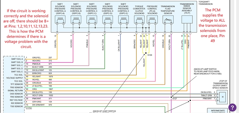
Figure 1
Therefore, the PCM immediately sets the P0962 and P0657 DTCs. The P0657 is set because the PCM could not read B+ from any of the solenoids, simple and logical. But why only P0962 and not a grocery list of solenoid codes like GM sets when there is no power? I have seen this in other algorithms in the past. The PCM does its self-test, the first solenoid it checks fails, it shuts the power off (relay or internal PCM switch), sets the code and it ignores the rest. On this one, however, P0657 hints to you that none of the solenoids had power to them because it is the actuator supply voltage, and there is none present at pin 49.
We've spent 10-15 minutes gathering data and using our knowledge of how these systems work, now let's get to truck and test our theory. Start with a battery and charging system analysis. Always make sure the battery and charging system are good and operating correctly. This vehicle passed the battery, alternator and, starting test.
I want the easiest way to test, so I'm going to locate the easiest place to access all the circuits. We'll start at the PCM, and it's located on the left side of the firewall. No lift is needed. If the vehicle runs ok and there are no other DTCs stored, you can assume your powers and grounds are ok, but don't assume; check the power supplies and perform a voltage drop test on the grounds. We did the appropriate testing, and all the circuits passed.
We located the C175C connector and the wire to the voltage supply, Yellow/White wire, pin 49 at PCM. I always pierce the wire to make sure I am connected. Back probing is another method, but I don't always know for sure if I've made a good connection. I set up my scope (DVOM is acceptable), KOEO and see what the reading is. I am expecting to see 0.0 volts coming out of the PCM. I have verified there is no supply voltage coming out of the PCM. I clear the codes and try again. This second test has confirmed there is no voltage (B+) coming out of the PCM. We have found the source of the problem. (Figure 2)
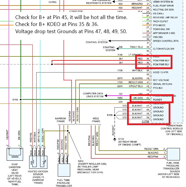
Figure 2
We have maybe an hour and possibly less invested in the complete process. We didn't have to lift the vehicle, unplug any circuit or pull any transmission pans. If you want to verify all your wires and solenoids are ok, unplug C175C, jumper a fused B+ wire to pin 49 and then ground each of the solenoid wires. If you have an amp clamp on the power wire you will be able to see the amperage each solenoids pulls and make sure they are within specs.
This is how I approach a situation like this one. It's a similar process on any electrical issue. You just need to know how the manufacturer operates their systems.