A customer brought her 2006 Chrysler PT Cruiser to our shop with a complaint of random high engine revs. She stated that restarting the engine resets the vehicle and it works again temporarily, and this had been going on for about four months. The vehicle had a 2.4-liter turbocharged engine with a 604 transmission.
The diagnostician performed the initial road test and collected some preliminary information. There were diagnostic trouble codes stored in the PCM. This was an NGC 4-plug computer, so the ECM and TCM are in the same module. The codes stored were P0700 (turns on the MIL), P1684 (battery was disconnected), and P0882 (TCM power input low). He was unable to duplicate the symptoms on the initial road test. There were also radio communication codes stored because the radio was not the factory radio. It also had an external audio amplifier and big subwoofers. At this point he was not sure if this is related, but took note of it. There was also a leak noted at the transmission pan, as well as a negative battery terminal in poor condition. The diagnostician recommended more diagnostic time to investigate the P0882 code and reseal the pan. The customer authorized the diagnostics and transmission service.
Battery connections are crucial in today's vehicles. A small amount of voltage loss can wreak havoc. The first step was to correct the connection problems. He replaced the negative battery terminal with a factory type cable end crimped onto the cable. The transmission was serviced to solve the leaking transmission pan, and the codes were cleared. The PCM calibration was checked and confirmed that it was up-to-date. The technician then drove the vehicle on multiple road tests to ensure the DTC would not reset. Confident that the poor battery connection solved the problem, the vehicle was delivered back to the owner that Friday afternoon.
The next Monday the vehicle came back. The owner stated that the light came back on and the vehicle quit shifting. The owner left the vehicle for us to check out. The technician ran the codes and the same P0882 was stored. An electrical system analysis was performed to confirm the battery and the charging system were functioning properly. It was time to look deeper into the P0882 code. A look at the repair manual would help us understand more about how the system works and conditions that cause the code to set. Per the manual:
Theory of Operation
The Transmission Control Output circuit is used to supply power to the Transmission Solenoid/TRS Assembly and to the PCM when in normal operating mode. The purpose of the Transmission Output circuit is to allow the Transmission Control System to turn off the power to the Transmission Solenoid/TRS Assembly in the event that the transmission should need to be placed into "limp-in" mode due to a DTC.
After a PCM reset, (ignition switch turned to the run position, or after cranking the engine) the Transmission Control System verifies that the Transmission Output circuit is open by checking for voltage on the Transmission Output circuits before the Transmission Control System request for the circuit to be powered up. The request is sent by a direct circuit control from the PCM to the TIPM. If the Transmission Control System detects less than 3.0 volts when the output is commanded on, the DTC will set.
Note: Inadequate Transmission Control Output voltage can also cause DTCs P0846, or P0871, to set. This does not indicate an internal transmission or solenoid/TRS problem. Repairing the P0882 fault should also eliminate the related DTCs.
When Monitored:
When the ignition is turned from "OFF" position to "RUN" position and/or the ignition is turned from "START" position to "RUN" position.
Set Condition:
This DTC is set when there is less than 3.0 volts present at the transmission control output circuits located in the Powertrain Control Module (PCM) when the Transmission Control System requests the power up of those circuits. Note: Due to the integration of the Transmission Control Module and the Powertrain Control Module, both systems have their own power and ground circuits."
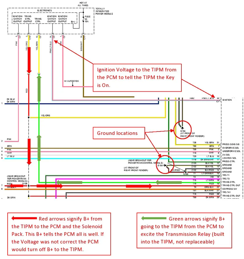
It seemed a little confusing. It took a few minutes and wire diagram to wrap my head around it. Basically, the PCM turns on the "relay" inside the TIPM to energize the solenoids. It also sends B+ back to the PCM on the same circuit to let the PCM know everything is "ON" and has no faults. If there was a fault and the TIPM turns off the solenoids, the PCM loses its B+ and registers a fault. (Figure 1)

Figure 1
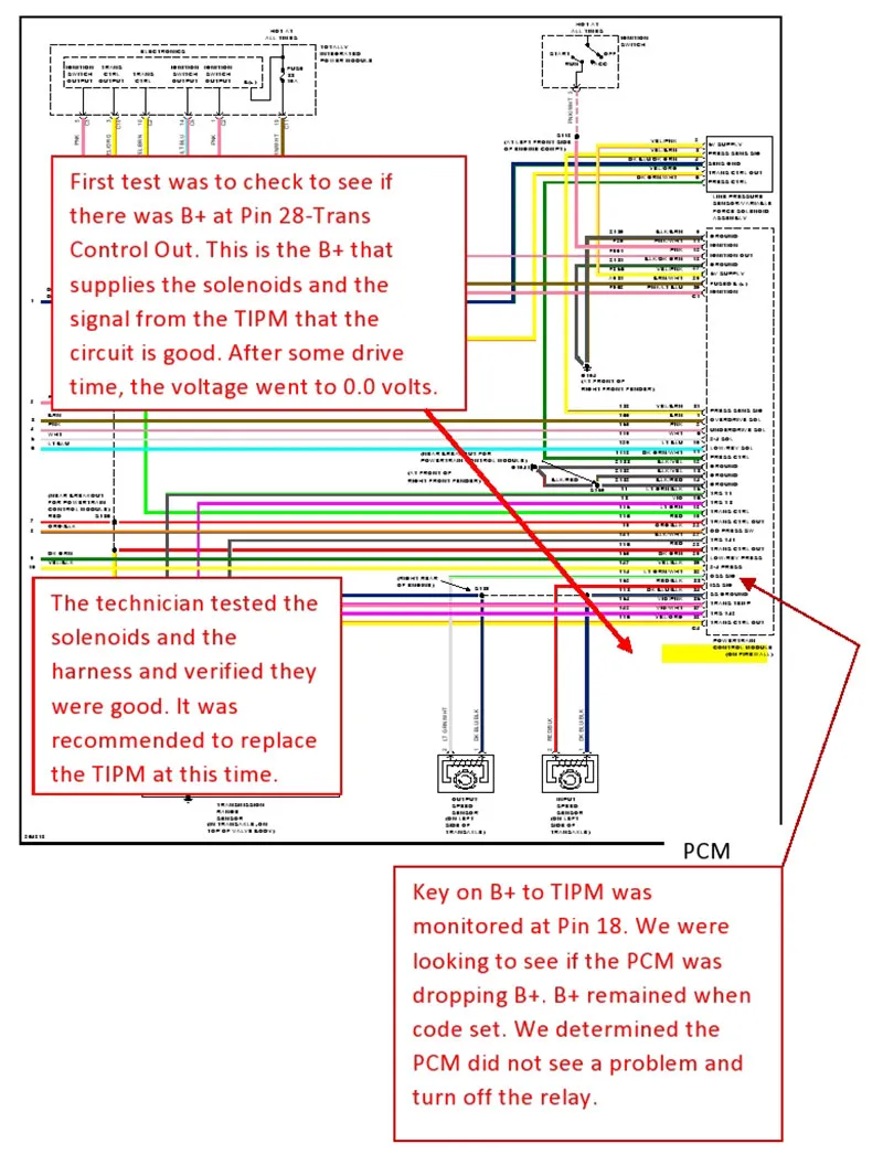
At this point we then decided to check to see if the B+ to the solenoids was present. This was an intermittent issue and it took several test drives for the problem to occur. Voltage was monitored with a DVOM at the PCM pin 28 (relay control out). When the problem occurred, the voltage went from B+ to 0 volts. According to the scan data, it appeared the TIPM was shutting off the power. Could there be an issue with the solenoid circuit? Testing concluded the solenoids and their circuits were good. Next, we need to know if the PCM is turning the trans control relay off. Pin 18, (transmission control voltage) was monitored. After several more test drives the code reset. Power to the TIPM, pin 18, was present at the time of the fault but, there was no power to the solenoids or to pin 28 at the PCM. (Figure 2)

Figure 2
It was concluded that the TIPM was at fault. Since the relay is internal to the TIPM we could not test or jumper the relay. A remanufactured TIPM was ordered from the dealer and installed. The vehicle was driven several more times and seemed to be fixed. The customer picked the vehicle up Friday afternoon.
I wish the story ended there, but it didn't. Monday the vehicle came back once again. As before, the warning lights were on and the transmission was not shifting. P0882 was stored but there was a new code that had not been there previously, P1603 (PCM internal dual-port ram communication failure).
This basically tells us there is an internal failure in the PCM. We need to check powers, grounds, and perform a wiggle test with the circuit live. No external problems were found so a replacement PCM was recommended. The customer opted for a used PCM. We installed the used PCM, updated the VIN and programmed it to the latest calibration. In the back of our minds was the thought, could this have been the source of all the P0882 issues? An internal PCM problem? After a week of road testing, the code had not reset. The customer picked the vehicle up just to bring it back an hour later.
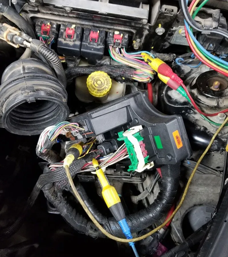
It seemed that we still hadn't conquered the P0882 code. We replaced the TIPM and the PCM. What else could it be? So many times we replace a component only to have the same problem. So, we assume the component is good because we just replaced it. We skip over the diagnostics to try and condemn something else. Continue where we left off. I have been guilty of this more times than I would like to admit. We have the same code, same symptoms. We could not assume anything and had to start from beginning. So, that's exactly what we did. Step one, attach scope equipment and start testing all over. We are now using a scope so we can see voltage over time. This should tell us which circuit is giving up first. (Figure 3)

Figure 3
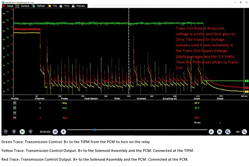
Now the code is setting about every other key cycle. While watching the Transmission Control Output we can see B+ dropping off. Shortly thereafter, we see the PCM turn off the B+ to the TIPM. (Figure 4)

Figure 4
So why is the voltage dropping out? Is there a problem the TIPM is seeing? It didn't appear so. If there was an issue with a solenoid or circuit, the voltage would be cut off immediately and not gradually/erratic cycle off like we saw in the scope capture, and we would likely have a DTC from the guilty component. We are going to test everything again anyway.
Again, we are going to test all the circuits controlled by the Transmission Control Output. We had no solenoid codes, but we were not going to assume anything at this point. So as to not to overlook the grounds, we performed a voltage drop test. We tested at the G104 grounds and got a reading of .008 V with the engine running.
With connector C10 disconnected from the TIPM and the C4 connector disconnected at the PCM, a resistance test was performed on each of the solenoids. I do not like to rely on resistance measurements alone, but since the circuit would not stay alive long enough to run the test through the scan tool and we could not jumper the relay, we had to settle for this test. Each of the circuits passed the resistance test without issue.
Once we determined nothing outside the TIPM was causing the issue, we condemned the TIPM. We called and had our faulty TIPM exchanged at the dealer. The TIPM was installed and the vehicle was driven. We drove the vehicle every day for over a week and the code did not return. We crossed our fingers and returned the vehicle to the customer. It's been well over a month now and happy to say we have not seen it back.
Second-guessing the parts we install is a tiresome prospect. In cases like this, sometimes it's the only option left to pursue. While it may make you feel like you are simply repeating diagnostics and the exercise is redundant, it may be the only way to solve the issue for your customer. Stay positive, and stay with it. Assume nothing. Just because a part is new, doesn't mean it's good.
 Certified Transmission
