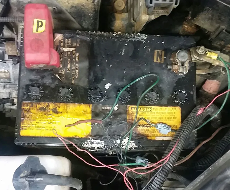
I wanted to share with you a couple of situations that I have run into over the past couple months. The first one is a 2010 Lexus RX350 that came in on the back of a tow truck. This SUV is equipped with a 3.5L V6 and a U660E transaxle. The customer had it towed because the vehicle was in fail safe mode. When I began the evaluation, the first thing I noticed was the strong odor of battery acid when I opened the hood. (figure 1) One look at the battery and I knew this was going to need to be addressed, but at this point I do not know what is causing the failsafe problem. When the scan tool was connected I discovered that I had no communication with the TCM, but did have communication with all of the other modules.

Figure 1
All of our initial diagnostic evaluations include a battery and charging system test. I'll bet you can guess the outcome of this one; the battery failed, but the alternator had passed. At this point we informed the customer that some electrical testing was going to be necessary in order for us to find out what was causing the problem. The customer agreed to that and we then proceeded with the job.
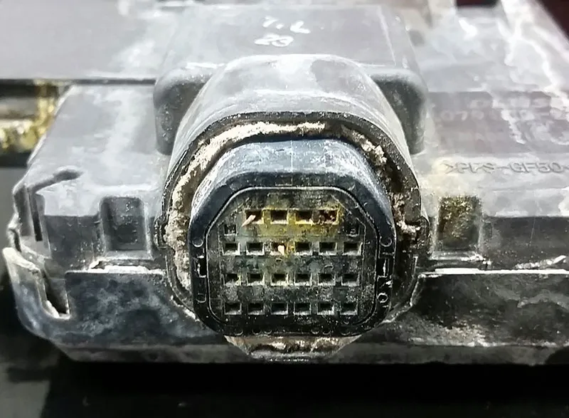
I am sure that you guys have seen these vehicles in your shop and know that the battery is positioned directly above the transaxle, so knowing that and the fact that the battery had evidence of leaking acid, I knew where I was headed. The TCM is mounted directly on top of the unit and plugs directly into the transmission case connector. I started by checking power and grounds on the vehicle harness to the TCM and found everything in order. I disconnected the harness and everything looked good with no corrosion or pin-fit connection issues. Next I removed the two bolts that hold the TCM to the case. The TCM just fell off onto the floor, and I was not expecting that! The case connector and the TCM were corroded so badly that four of the pins and the plastic housing were stuck in the TCM. (figures 2 and 3) I think I found the problem! My next move was to recommend a pan inspection to see if there was any need to go inside the transmission, or just replace the internal harness and TCM. After dropping the pan it looked good inside, no clutch material or excessive metal. I then recommended replacing the internal harness, TCM, battery, and a transmission fluid flush.

Figure 2

Figure 3
The parts were a couple of days out, so while I was playing the waiting game I cleaned the area as best I could and installed the new battery. When the parts arrived I pulled the valve body down and replaced the internal harness, installed the TCM, and flushed the transmission fluid. The TCM came already loaded with the calibration so all I needed to do was the initialization procedure, reset memory as Toyota/Lexus call it, and go for a road test. The transmission shifted as it should and I couldn't be more pleased. The customer was also pretty happy that they did not need to replace the transmission.
The next vehicle I wanted to discuss had an issue that you will not see that often. The car was a 2006 Hyundai Tiburon with a 2.0 liter 4 cylinder with an A4BF1 transmission. While going through the initial evaluation and connecting the scan tool, it had a DTC stored for P0711 TFT signal abnormal, but no other codes. The customer concern was that everything seemed to work fine but, the CEL light would "come and go".
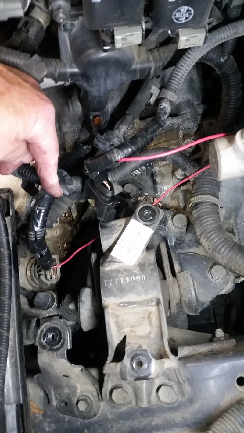
With the scanner attached and the transmission data PIDs on the screen, I could see that the transmission temperature was 45?F which was fairly close to the ambient temperature at the time. That, coupled with the customer concern, I was expecting an intermittent issue. As I took off on the road test the transmission shifted well but the TFT PID never went above 45?F, so therefore the TCC never engaged. This appeared to be what was causing the code to set, so I needed to find the root cause of the issue. After returning to the shop and pulling onto the lift, I started taking a closer look in the area of the transmission and noticed an extra red wire in the loom to the mass air flow sensor, as seen in the photo (figure 4).

Figure 4
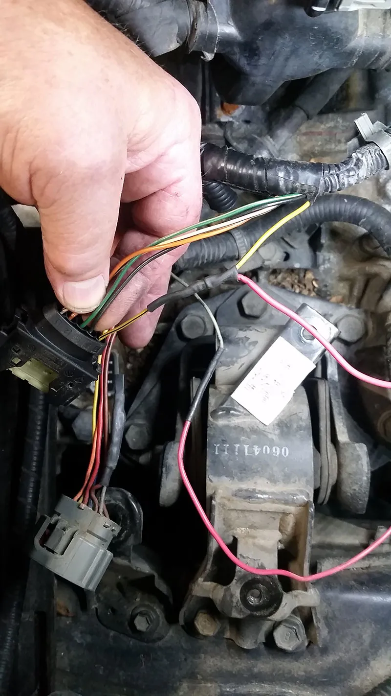
After peeling the tape and wiring loom off the red wire, I could see that it was spliced into the yellow/black wire in cavity #5 of the MAF sensor pigtail. The other end of the wire was spliced into the gray wire cavity #1 of the transmission case connector, which is for the TFT sensor. (figure 5) I talked to a couple of colleagues about this but they had never seen nor heard of this scenario. I even tried the tech support search, but nothing came up. My theory is they were trying to trick the ECM into thinking it was running cold so it would richen up the fuel mixture and supposedly get better power and performance. I just could not figure out why we went to the transmission temp sensor. Maybe they were trying to have the IAT temp and transmission temp match? I wish I knew what went through some of these people's thought pro-cesses.

Figure 5
After returning everything back to a factory configuration, I serviced the transmission and went for another road test. Watching the scanner, the TFT sensor was rising as it should, and when it was warm enough the TCC would now engage as it was designed to. We called and let the customer know his car now works like it should and he was happy that the source of the intermittent CEL was solved. Both cases could have turned out worse for the customers, but a happy customer means repeat business.
 Certified Transmission
